


GİRİŞ TEKNE KESİTLERİ VE GÖVDE BİÇİMLERİ GENEL DENİZCİLİK TERİMLERİ VE TEKNEDE YÖNLER MOTORLU TEKNELER YELKENLİ TEKNELER HALATLAR, BAĞLAR VE BAĞLAMA(PALAMAR) HALATLARI MANEVRAYI ETKİLEYEN FAKTÖRLER AYRILMA VE YANAŞMA(AVARA VE ABORDA) DEMİRLEME (FUNDA VE VİRA DEMİR) DENİZ KAZALARI VE CAN KURTARMA ARAÇLARI DENİZE ADAM DÜŞMESİ DENİZDE ÇATIŞMA VE ÇATIŞMA SONRASI ALINACAK ÖNLEMLER GEMİNİN KARAYA OTURMASI YEDEKLEME VE YEDEKLENME YANGIN TEKNEYİ TERK VE DENİZDE CANLI KALMA TEKNEDE İLK YARDIM VE SAĞLIK KLAVUZU METEOROLOJİ NAVİGASYON/SEYİR DENİZDE ÇATIŞMAYI ÖNLEME TÜZÜĞÜ DENİZ HUKUKU VE U/A SÖZLEŞMELER MOTOR ELEKTRİK
AMATÖR DENİZCİ BELGESİ SINAVINA HAZIRLIK KURSU KURAMSAL DERS PROGRAMI MODÜLLERİ
MODÜL 1/GÜN 1 DERS 1 KONU: Giriş – Tarihçe Ve Genel Güvenlik (ADEK BÖLÜM – 1)
KONU: Tekne Kesitleri Ve Gövde Biçimleri (ADEK BÖLÜM – 2)
KONU: Genel Denizcilik Terimleri Ve Teknede Yönler ( ADEK BÖLÜM – 3 )
DERS 2
KONU: Motorlu Tekneler ( ADEK BÖLÜM – 4 )
KONU: Yelkenli Tekneler ( ADEK BÖLÜM – 5 )
DERS 3
KONU: Halatlar, Bağlar Ve Bağlama Halatları (ADEK BÖLÜM – 6 )
KONU: Manevrayı Etkileyen Faktörler ( ADEK BÖLÜM – 7 )
KONU: Ayrılma Ve Yanaşma (Avara Ve Aborda) (ADEK BÖLÜM – 8 )
MODÜL 2/GÜN2
DERS 4
KONU: Navigasyon (Seyir) (ADEK BÖLÜM – 19 )
DERS 5
KONU: Denizde Çatışmayı Önleme ( ADEK BÖLÜM – 20 )
MODÜL 3/GÜN 3
DERS 6 KONU: Demirleme ( ADEK BÖLÜM - 9 ) DERS 7 KONU: Deniz Kazaları Ve Can Kurtarma Araçları (ADEK BÖLÜM – 10) KONU: Denize Adam Düşmesi ( ADEK BÖLÜM - 11 ) DERS 8 KONU: Denizde Çatışma Ve Çatışma Sonrası Alınacak Önlemler (ADEK BÖLÜM -12) KONU: Teknenin Karaya Oturması (ADEK BÖLÜM.-13 ) KONU: Yedekleme ve Yedeklenme ( ADEK BÖLÜM.-14 )
MODUL 4/GÜN 4
DERS 9 KONU: Yangın ( ADEK BÖLÜM – 15 ) DERS 10 KONU: Tekneyi Terk Ve Denizde Canlı Kalma (ADEK BÖLÜM - 16) DERS 11 KONU: Teknede İlk Yardım Ve Sağlık Kılavuzu (ADEK BÖLÜM – 17 ) DERS 12 KONU: Meteoroloji (ADEK BÖLÜM – 18 )
MODÜL 5/GÜN 5
DERS 13 KONU: Deniz Hukuku Ve Uluslar Arası Sözleşmeler (ADEK BÖLÜM – 21 ) DERS 14 KONU: Motor (ADEK BÖLÜM – 22 ) DERS 15 KONU: Elektrik ( ADEK BÖLÜM – 23 )
SİNTİNE
KARİNA KARİNA OMURGA
GÜVERTE
W L
ALABANDA ALABANDA
SU HAT TI
B O R D A
TEKNE EMNİYET CHECK LİST
KORUCU KİYAFETLERİNİZİ GİYDİNİZ Mİ? TEKNEDEKİ GÖREVİNİZİ BİLİYOR MUSUNUZ? CAN YELEĞİNİZİ GİYDİNİZ Mİ? EMERCENSİ İŞARET FİŞEĞİNİN YERİNİ BİLİYOR MUSUNUZ? YANGIN SÖNDÜRÜCÜYÜ KULLANMAYI BİLİYOR MUSUNUZ? CAN SALINI ATMAYI BİLİYOR MUSUNUZ? TELSİZ MESAJI GÖNDERMEYİ BİYOR MUSUNUZ?
AŞAĞIDAKİ KONULARI ÖNCELİKLE ÖĞRENİNİZ EĞİTİM YAPACAĞINIZ TEKNENİN PARÇALARININ GEMİCİ DİLİNDEKİ KARŞILIKLARI SEYİR ESNASINDA TEKNENİN KULLANIMINI ÖNEMLİ GEMİCİ BAĞLARI VE NASIL KULLANILDIĞINI HALATLARIN İSİMLERİ VE KULLANILIŞLARI DENİZE ADAM DÜŞTÜ KURALLARINI LİMANDA TEKNE BULUNDURMA ŞARTLARINI HAVA TAHMİNİ DÜMEN VE TEKNE KULLANIMINI
TEKNE MÜRETTEBATI KİŞİSEL ÇEK LİSTESİ (EĞİTİM)
Aborda” olmak Bir teknenin, bir baska tekneye, rıhtıma veya iskeleye bordasını vererek yanasmasına aborda denir.
Avara olmak Teknenin yanasık oldugu yerden ayrılmasına avara olmak denir. Alargada olmak Bir teknenin sahilden açıkta durması, beklemesi durumuna alarga denir. Usturmaça Teknenin iskeleye veya baska bir tekne üzerine baglanırken zarar görmemesi için araya koyulan sentetik maddelerden yapılmıs balon veya silindir seklindeki yastıklara usturmaça denir. Alabora olmak Bir teknenin ters dönmesine alabora denir.
Hisa Herhangi bir seyin (yelken gibi) yukarı kaldırılmasına, çekilmesine hisa denir. Vira Halatın çekilmesi ( almak) veya yükseltilmesi için verilen komut viradır. Mayna Bir yükün indirilmesi, asagı dogru yavasça bırakılması için verilen komut maynadır.
Laçka Halatın tamamen elden çıkartılmadan, boslanması için verilen komut laçkadır.
Fora Bir yere baglı halat veya düzenegin çözülmesi, çıkarılması, açılması için verilen komut foradır.
Volta Halatın koçboynuzu, anele gibi yerlere baglanması için verilen komut voltadır. Toka Bir cismin istenilen yere çıkartılması veya bir flama veya sancagın gönderdeki yerine çekilmesi için verilen komut tokadır.
Arya Bir halat yardımıyla yukarı çekilmis yelken, bayrak, flama gibi gibi seylerin asagı indirilmesi için verilen komut aryadır.
Arma Yelkenli teknelerde, direk ve yelken ile ilgili özellikleri kapsayan genel terimdir
Lumboz Bordalara açılmıs ve teknenin içine hava ve ısık girmesini saglayan sızdırmaz pencerelerdir Güverte Kemerelerin üstünü kaplayan ve bastan kıça uzanan alana verilen ad
Irgat Teknelerde basta bulunan, halat ve demir manevralarında kullanılan mekanizmaya verilen ad
Istralya Bir teknede diregi bas-kıç dogrultusunda destekleyen tellere ıstralya denir. Çarmıh Bir teknede diregi bordalar istikametinde destekleyen ve iki yandan tekne gövdesine baglayan tel veya çubuga çarmıh denir. Iskota Yelkeni kontrol eden ve kontrol ettigi yelkene gore isimlendirilen halata ıskota denir.
Mandar Yelkeni basıp, indirmeye yarar.
Seren Yelkenli teknelerde diregin orta boyunda veya daha yukarısında, çarmıhları iki yana dogru açan metal veya ahsap çıkıntılara ne ad verilir?
FUNDA demir atılması için verilecek komuttur.
VİRA DEMİR demir alınması için verilen komut AGANTA Hareket halindeki zincirin akısının durdurulması için verilmesi gerek komut BOSA TUTMAK/ BOSAYA VURMAK Ani gerilimlerden ırgatın dislilerinin zarar görmemesi için, demir zinciri veya halatın yükünün bir halat aracılıgıyla alınıp, bir koç boynuzuna veya babaya aktarma
ÇIMA
KRUZ HALATIN BEDENİ
DÜĞÜM
KROPİ
BALIKÇI
DÜLGER BAĞI Bir halatın çımasını bir seren benzeri yere bağlamak için kullanılan bir bağdır. Bağlanması ve çözülmesi çok kolaydır
ANELE BAĞI Bir halatın çımasını demir anelesine veya diğer herhangi bir aneleye bağlamak için kullanılan bağdır
KAZIK BAĞI Bir halatı sahilde herhangi bir yere bağlamak, veya halat çımasını puntel, vardevela vb. gibi iki ucu kapalı yerlere bağlamakta kullanılır
ÇİFTE KAZIK BAĞI Kazık bağının çift veya daha fazla voltalısıdır. Yelkenleri matafyonlarından serenlere, çarmık iskalaryalarını çarmıklara ve tenteleri vardevelaya bağlamak için kullanılır.
MARGARİTA BAĞI Bedeni kol atmış bir halatı kesmeden aynı güçte kullanmak maksadı ile yapılan bir bağdır. Ayrıca halat boylarını kısa tutmak maksadı ile de kullanılır.
SANCAK VEYA İSKOTA BAĞI Sancak salvolarını birbirine bağlamaya, halat çımasını bir makara bülbülün veya radansalı bir kasaya bağlanmasını sağlayan bağdır
İZBARÇO BAĞI
Halat bedeni üzerinde geçici kasa oluşturmak üzere yapılır. Ayrıca direk vb. gibi yüksek yerlerde çalışacak personel için emniyet maksatları ile kullanılır
Sıkışmaz - kaymaz ve kolayca açılır
CAMADAN BAĞI Yelkenlerin camadana vurulması, sert rüzgarlarda yelken küçültmek için camadan kalçatalarının birbirine bağlanması maksadıyla kullanılır.
YOMA BAĞI Farklı burgatalarda olan 2 halatın birbirine bağlanmasında kullanılır.Camadan bağının farklı bir uygulamasıdır
KANCA BAĞI Çıması kısa kalmış bir halatı bir palanga kancasına bağlamak için yapılan bir krozdur. Yük bindikçe sıkışma özelliği vardır
BARBARİŞKA
Irgat veya vinç yardımı ile boşu alınmış bir halatın babaya voltası amacıyla kaçırmadan tutmak için halat bedenine ince bir halat ile mezevolta alınıp onun bükümü yönüne sarılmasıdır
PALAMAR HALATLARI
1. BAŞ HALATI 2. BAŞ KOLTUK 3. KIÇA KUMANDALI BAŞ PÜRMEÇE (BAŞ SPRING) 4. BAŞA KUMANDALI KIÇ PÜRMEÇE (KIÇ SPRING) 5. KIÇ KOLTUK 6. KIÇ HALAT
MANEVRAYA ETKİ EDEN UNSURLAR
DOĞA ŞARTLARINDA BİR GEMİNİN MANEVRASINA ETKİ EDEN UNSURLAR;
1. PERVANE TESİRİ A. MERKEZİ ETKİ B. ENİNE ETKİ (PADIL TESİRİ) 2. DÜMEN TESİRİ 3. RÜZGAR TESİRİ 4. AKINTI ETKİSİ
SAĞA DEVİRLİ PERVANE İLERİ YOLDA KIÇ SANCAĞA TORNİSTANDA İSKELEYE ÇEKER
RÜZGAR BAŞTAN ESERKEN AVARA ETME
RÜZGAR KIÇTAN ESERKEN AVARA ETME
WIND
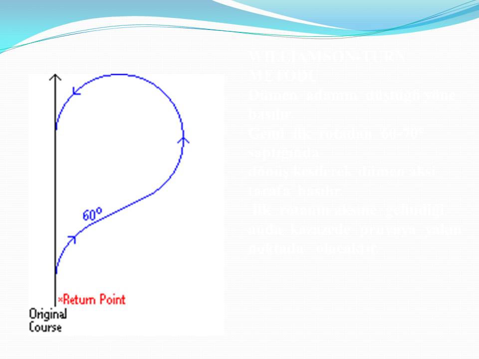
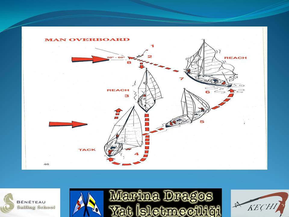
ANDERSON (DAİRE) DÖNÜŞÜ
WILLIAMSON-TURN METODU Dümen adamın düştüğü yöne basılır. Gemi ilk rotadan 60-70° saptığında dönüş kesilerek dümen aksi tarafa basılır. İlk rotanın aksine gelindiği anda kazazede pruvaya yakın noktada olacaktır.
Çatısma halinde ilk yapılması gereken nedir? Önce can emniyeti saglanır sonra teknenin su yapıp yapmadıgı kontrol edilir.
Çatısma sonrası, suyu kesmek için gerekli önlemleri aldıgınız halde batma ihtimaliniz varsa ne yapılmalıdır? Ne kadar zaman teknenin yüzmeye devam edecegi hesaplanır.
Karaya oturmus bir tekne, oturulan bölge hakkında hiç bir bilgi elde edilememisse, öncelikle hangi yönde yüzdürülmeye çalısılmalıdır? Oturdugu yönde (tornistan yaparak)
Karaya oturmus bir teknenin, yardım almadan tekrar yüzdürülmesi hangi yöntemle saglanabilir? Motorla, agırlıgı bir tarafa vererek, agırlıgı azaltarak
Bir teknenin isteyerek karaya oturtulması halinde, üzerinde ne kadar yol olmalıdır? Dümen dinleyecek kadar bir yol
Bir tekne isteyerek karaya oturtulurken tekrar yüzdürülecegi düsünülerek ne yapılmalıdır? Kıç demiri atılmalıdır
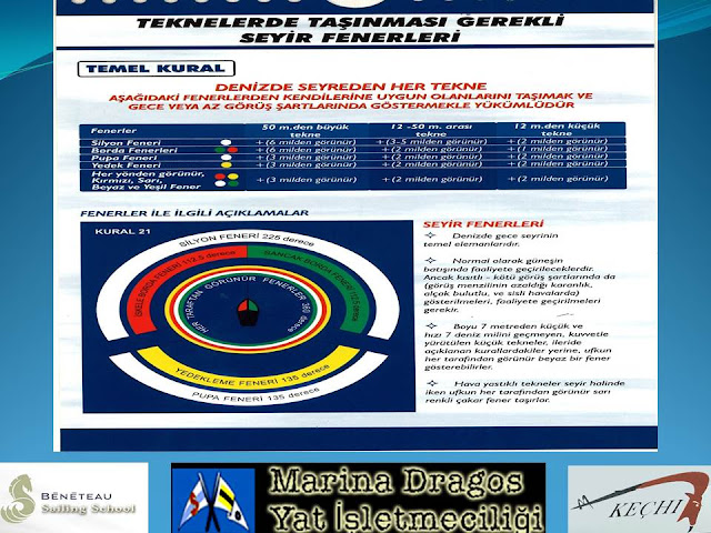
Lights, Less Than 65.6 Feet /20 Meters
Lights Less Than 39.4 Feet / 12 Meters
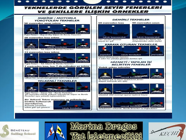
Sailing Vessel Underway
Figure 22–10 Option, Sailing Vessel
Combination Lantern
Less Than 23 Feet / 7 Meters
Under Sail and Power
Under Oars
Fishing Boat Trawling
Red over White. Fishing at Night
Port to Port
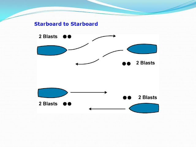
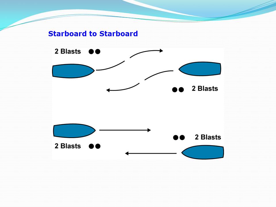
Starboard to Starboard
Overtaking, Leave to Port
Overtaking. Leave to Starboard
KAPTANIN SEYİR İLE İLGİLİ SORUMLULUKLARI
LİMAN İŞLEMLERİ
ÖZEL TEKNELERİ KULLANMAK İÇİN GEREKEN YETERLİLİKLER
SAHİL SIHHIYE MEVZUATI
GÜMRÜK MEVZUATI
DENİZ KİRLİLİĞİ-MARPOL
DENİZ CANLILARININ KORUNMASI
TEKNE SİGORTALARI
ELEKTRİK SİSTEMLERİ AKÜLER
KABLOLAR
KUMANDA PANASU
SİGORTA VE OTOMATLAR
TÜKETEÇLER
ELEKTROLİT KOROZYON
YILDIRIMDAN KORUNMA
Nautical Charts
Projections The nautical chart is a 2-dimensional representation of a 3- dimensional world. A well known method to create such a chart is called the Mercator projection after Gerard “Mercator” Kremer , a Flemish scholar who studied in 's Hertogenbosch (the Netherlands) and Leuven (now Belgium) and who invented his famous projection in 1569.
The Mercator chart was designed for sailors and can be constructed by wrapping a cylinder around the planet so that it touches the equator. On this cylinder the surface of the earth is projected and finally the cylinder is cut open to yield the 2- dimensional chart.
The Mercator Chart
Organization of the chart •Authority: The publisher responsible for the information in the chart – “British Admiralty Charts”. •Title: The title gives a description of the area covered by the chart – “The Aegean Sea of Greece - Athens to Rhodes”. •Number: Different chart types of the same area can be distinguished by the chart's number. •Projection: Most likely the Mercator projection as described above. Charts covering small areas can be constructed by stereographic projection. •Scale: For example: 1:193.000. But since the chart is distorted this holds only for one specific latitude in the Mercator chart. The scale indicates how detailed the chart is (here 1 cm on the chart represents 193000 cm on earth). •Horizontal geodetic datum: The definition of the relationship between the ellipsoid adopted as the model of the Earth's shape, and the Earth itself. Though there are hundreds of datums in use, most are only locally valid. Yet, the WGS-84 datum is global in scope and positions obtained by satellite navigation systems are usually referred to this datum. Therefore, a correction needs to be applied to a WGS-84 GPS position to agree with charts using other horizontal datums. For example to correct WGS-84 to the European datum, add 0,06'N , 0,04'E (style guide) to the WGS-84 position indicated by the GPS. Fortunately, most GPS receivers may be set to display positions in several other datums besides WGS-84 and perform the calculations for you. •Chart sounding datum: The tidal datum to which soundings and drying heights on a chart are referred. Often shortened to “chart datum” when it is clear that reference is not being made to a horizontal datum. Chart sounding datums are also used as reference for heights (lighthouses, mountains, bridges). Multiple datums can be used in one chart: L.A.T. for soundings and M.L. for heights. See chapter 6. •Soundings & height units: Soundings and heights can be stated in - for example - metres, feet or fathoms. Today all charts worldwide are metric, except for USA Hydrographic Office charts, which sometimes still use feet instead of the international standard. •Horizontal scale: Natural scale at for example 40° 15,3' S latitude where the horizontal scale can be used for measuring distances and where the chart scale is true. •GPS compatibility: Most charts neither have the precision nor the resolution to fully use the (differential) GPS positioning potential. Moreover, still plenty of charts result from surveys done in the 19th century. Also, GPS data often requires a correction for a local horizontal chart datum before it can be used in the chart. •Corrections & edition: The chart is for example a 2009 edition but is - when properly corrected - still valid in 2012. Corrections are published continuously and the changes made should be mentioned in the bottom left corner of the chart.
Information in the chart •Depths reduced to chart datum: A sounding like 35 indicates 3½ metres of water under Lowest Astronomical Tide (when the chart datum is “L.A.T.”). An underlined sounding like 04 indicates a height of 40 cm above L.A.T.. Heights above Chart Datum on drying areas are given in metres and decimetres. The metres figure is underlined. Depths are given from 0.1 to 20.9 in metres and decimetres, and from 21 to 31 in metres and half metres. Greater depths are rounded down to the nearest safest metre (for example, 32.7 metres is rounded down to 32 metres). The geographical position of a sounding is the centre of the depth figure. •Isobaths: Lines connecting positions with the same depth: depth contours. •Heights reduced to chart datum: Heights of for instance, lighthouses, mountains and cliffs are more often reduced to another datum such as Mean High Water (M.H.W.) or Mean High Water Spring. •Tidal information: Details of both the vertical and the horizontal movement of the water is often included in the chart. •Lighthouses, Buoys & marks: Lights, lateral and cardinal marks, see •Seabed qualities: Pebbles, seaweed, rocks, wrecks, pipelines, sand and other •Magnetic variation: The angle between the true North and the magnetic North varies in place and time. The local variation is indicated in the compass card , see •Landmarks: conspicuous positions on the shore: Churches, radio masts, mountain tops, etc. that can be used for compass bearings and other means of navigation, these will be put to good use in
Danger mark 32° 06,3' N , 25° 07,3' E
Fish farm 32° 04,4' N , 24° 54,7' E Anchorage 31° 46,0' N , 25° 04,0' E Church 31° 48,4' N , 25° 25,0' E Windmill 32° 01,0' N , 24° 57,8' E Castle 32° 14,2' N , 25° 29,6' E Water tower 31° 54,9' N , 24° 54,8' E Radio mast 31° 54,8' N , 25° 10,0' E Beacon green 31° 52,0' N , 24° 44,3' E
Coordinates and positions
A pair of nautical dividers (single handed dividers) is used to obtain precise coordinates from the chart. This device enables you to take the distance between that particular position and the closest grid line. You then place the dividers on the scale with one end on this grid line, leaving the other end precisely at your coordinate. Do this twice to get both latitude and longitude at the scale on the edge of the chart.
Below are some examples.
Distances To measure the distance between, for instance, these two oil rigs, we will again need our dividers. Remember, we can only use the vertical scale. We first take a convenient distance like 10' (10 nautical miles) on the vertical scale using the middle latitude. Then we start walking with the dividers from the southern oil rig to northern one. Finally, we adjust the dividers to measure the small remaining part at its own height, i.e. its own latitude . The image shows that the total distance is 37 nautical miles.
Courses
So, now we can measure distances and both plot and read out positions, but we also need directions. For example we need to find the course from safe-water buoy A to safe-water buoy B. To accomplish this we may use parallel rules as shown in this chart below:
First you line this instrument up with the two buoys. Then follows the intriguing part in moving the device to the compass rose without losing its alignment. Finally, when one of the rules is aligned with the heart of the compass card, you can read course A – B. In this example: 170°. Besides the parallel rules there are other types of instruments available, notably the Breton plotter - also known as a Portland Course Plotter - which features an adjustable rose.
Compass Navigation
Magnetic Variation In the sixteenth century mariners believed that the magnetic north pole coincided with the geographic north pole. Magnetic observations made by explorers in subsequent decades showed however that these suggestions were true. But it took until the early nineteenth century, to pinpoint the magnetic north pole somewhere in Arctic Canada (78° N , 104° W).
From then on the angle between the true North and the Magnetic North could be precisely corrected for. This correction angle is called magnetic variation or declination.
It is believed that the Earth's magnetic field is produced by electrical currents that originate in the hot, liquid, outer core of the rotating Earth. The flow of electric currents in this core is continually changing, so the magnetic field produced by those currents also changes.
This means that at the surface of the Earth, both the strength and direction of the magnetic field will vary over the years. This gradual change is called the secular variation of the magnetic field. Therefore, variation changes not only with the location of a vessel on the earth but also varies in time.
Magnetic Variation
The correction for magnetic variation for your location is shown on the nearest Nautical Chart's Compass Rose.
In this example we find a variation of 4° 15' W in 2009, with an indicated annual correction of 0° 08' E. Hence, in 2011 this variation is estimated to be 3° 59', almost 4° West. This means that if we sail 90° on the chart (the true course), the compass would read 94°.
Another example: let's say the compass rose gives a variation of 2° 50' E in 2007, with a correction of 0° 04' E per year. In 2009 this variation is estimated to be 2° 58', almost 3° East. Now, if we sail 90° on the chart, the compass would read 87°.
These overlayed compass roses show the difference between true north and magnetic north when the magnetic variation is 10° West. From the image we find: tc = cc + var in which “cc” and “tc” stand for “compass course” and “true course”, respectively. To convert a true course into a compass course we need first assign a “-” to a Western and a “+” to a Eastern variation. Note that this makes sense! because of the clockwise direction of the compass rose. Here, the inner circle is turned 10° anticlockwise, hence -10° . Now, use the same but re-written equation: cc = tc - var 235° = 225° - (-10°) So, to sail a true course of 225°, the helmsman has to steer a compass course of 235°.
To convert a compass course into a true course we can use the original equation. If we have steered a compass course of 200°, we have to plot a true course of 203° in the chart if the variation is 3° East or a true course of 190° if the variation is 10° West .
Correcting for variation
Magnetic deviation is the second correctable error. The deviation error is caused by magnetic forces within your particular boat. Pieces of metal, such as an engine or an anchor, can cause magnetic forces. And also stereo and other electric equipment or wiring, if too close to the compass, introduce errors in compass heading. Furthermore, the deviation changes with the ship's heading, resulting in a deviation table as shown below. The vertical axis states the correction in degrees West or East, where East is again positive. The horizontal axis states the ship's heading in degrees divided by ten. Thus, when you sail a compass course of 220°, the deviation is 4° W. (Note, that on most modern sailing yachts the deviation is usually not larger than 3°). When a compass is newly installed it often shows larger deviations than this and needs compensation by carefully placing small magnets around the compass. It is the remaining error that is shown in your deviation table. You can check your table every now and then by placing your boat in the line of a pair of leading lights and turning her 360 degrees. Magnetic deviation
Converting a compass course into a true course, we can still use our equation but we need to add the correction for deviation: cc + var + dev = tc
Example 1: The compass course is 330°, the deviation is +3° (table) and the variation is +3° (chart); 330° cc + 3° var + 3° dev = ?° tc giving a true course of 336° which we can plot in our chart
Example 2: The compass course is 220°, the deviation is -4° (table) and the variation is still +3° (chart). 220° cc + 3° var + -4° dev = ?° tc giving a true course of 219°.
Example 3: The compass course is still 220°, therefore the deviation is still -4° (table) but let's use a variation of -10° this time. 220° cc + -10° var + -4° dev = ?° tc giving a true course of 206°.
Correcting for both deviation and variation
Converting a true course into a compass course is a little less straight forward, but it is still done with the same equation.
Example 4: The true course from the chart is 305° and the variation is +3° (chart), yet we don't know the deviation; ?° cc + 3° var + ?° dev = 305° tc Luckily, we can rewrite this so this reads: cc + dev = 305° tc - + 3° var = 302° In plain English: the difference between the true course and the variation (305 - + 3) = 302 should also be the summation of the compass course and the deviation. So, we can tell our helms person to steer 300°, since with a cc of 300° we have a deviation of +2° (As can be deduced from the deviation table above).
Example 5: The true course from the chart is 150° and we have a Western variation of 7 degrees (-7°). We will use the rewritten equation to get: 150° tc - - 7° var = cc + dev = 157° From the deviation table we find a compass course of 160° with a deviation of -3°.
Correcting for both deviation and variation
The magnetic course (mc) is the heading after magnetic variation has been considered, but without compensation for magnetic deviation. This means that we are dealing with the rewritten equation from above: tc - var = cc + dev = mc.
Magnetic courses are used for three reasons:
1.To convert a true course into a compass course like we saw in the last paragraph. 2.On vessels with more than one steering compass, also more deviation tables are in use; hence only a magnetic or true course is plotted in the chart. 3.Bearings taken with a handheld compass often don't require a correction for deviation, and are therefore useful to plot in the chart as magnetic courses. Note, that the actual course lines the navigator draws in the chart are always true courses! These can subsequently be labeled with the true course or the corresponding magnetic or compass course if appropriate. To summarise, we have three types of “north” (true, magnetic and compass north) like we have three types of courses: tc, mc and cc. All these are related by deviation and variation.
Magnetic course


Hiç yorum yok:
Yorum Gönder